Beginner Friendly

Master ESP32 Programming from Zero

Build incredible IoT projects with the world's most popular microcontroller. From blinking LEDs to WiFi-connected dashboards — no prior experience needed.

12
Modules
25+
Examples
🔎
Circuit Lab
20
Quiz Q's

📋 Course Overview

This course takes you from absolute beginner to confident ESP32 developer. Each module builds upon the previous one, with hands-on examples, interactive simulators, and video tutorials.

Module 1

What is ESP32?

Hardware, specs, architecture & pin explorer
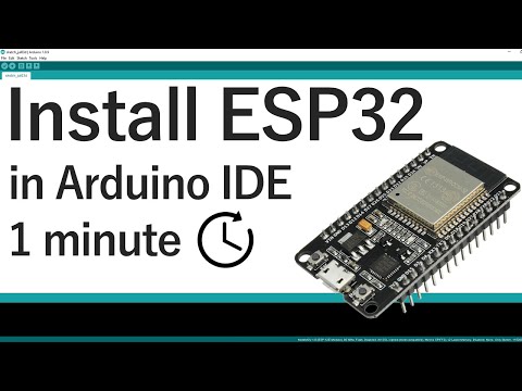
Module 2

Arduino IDE Setup

Install & configure your dev environment

Module 3

Your First Program

Blink LED + interactive LED simulator

Module 4

GPIO & Digital I/O

Buttons, LEDs, traffic light project

Module 5

Analog & PWM

Sensors + PWM waveform visualizer

Module 6

Serial Communication

Debug + interactive serial simulator

Module 7

WiFi Basics

Station, Access Point, WiFi scanner

Module 8

Web Server

Control hardware from any browser

Module 9

Sensors & Displays

DHT22, OLED, I2C wiring

Module 10

IoT Dashboard

Capstone: WiFi weather station

⭐ New

Interactive Circuit Lab

Drag & drop ESP32 breadboard simulator!

Assessment

Final Quiz

20 questions to test your knowledge
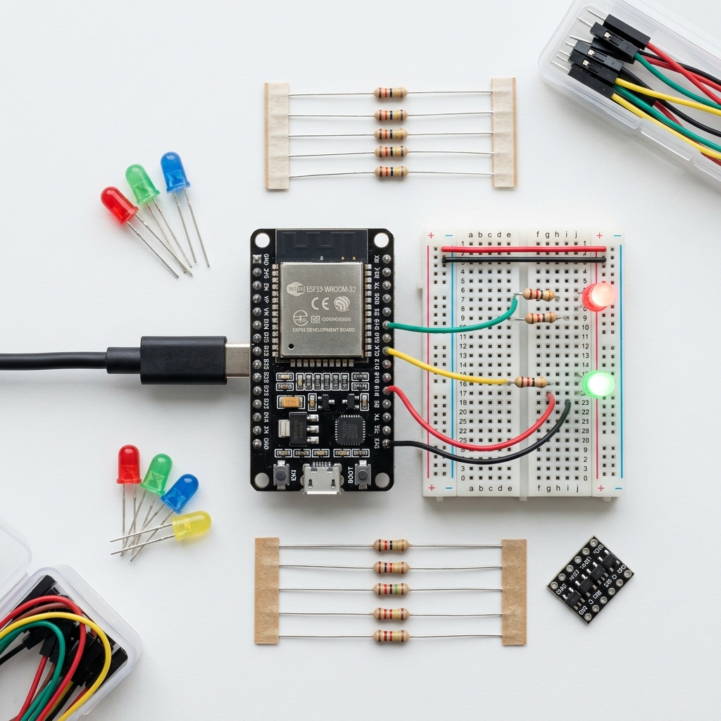
🧰 What You'll Need

🔧
ESP32 Dev Board

Any ESP32 DevKit v1 or similar (~$5-10)

🔌
USB Cable

Micro-USB or USB-C data cable

🍞
Breadboard

Solderless breadboard + jumper wires

ðŸ’Ą
LEDs & Resistors

Assorted LEDs + 220ÎĐ resistors

ðŸŒĄïļ
DHT22 Sensor

Temperature & humidity sensor

📚
OLED Display

0.96" I2C SSD1306 display

Module 1

What is ESP32?

Understand the hardware, specifications, and capabilities of the most popular IoT microcontroller.

🔍 Overview

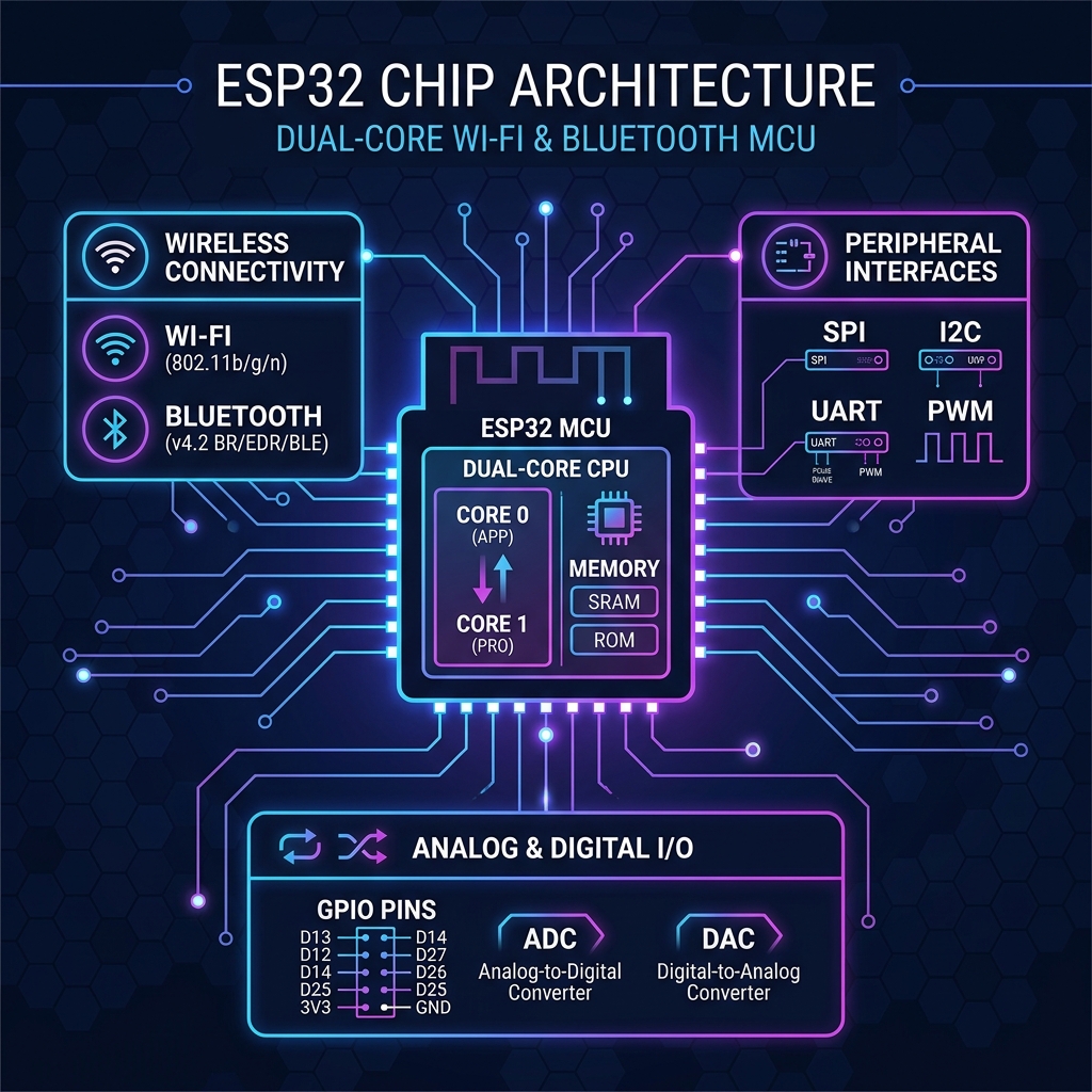
The ESP32 is a powerful, low-cost microcontroller made by Espressif Systems. It combines a dual-core processor, WiFi, Bluetooth, and dozens of I/O pins — all on a tiny chip that costs around $3-5.

Think of it as a small, affordable computer that can connect to the internet and interact with the physical world through sensors, motors, LEDs, and more.

ESP32 Dev Board
Figure 1.1 — ESP32 Development Board with common accessories

⚡ Key Specifications

FeatureSpecification
ProcessorDual-core Xtensa LX6, up to 240 MHz
RAM520 KB SRAM
Flash4 MB (external, varies by board)
WiFi802.11 b/g/n (2.4 GHz)
BluetoothBluetooth 4.2 + BLE
GPIO Pins34 programmable pins
ADC18 channels, 12-bit resolution
DAC2 channels, 8-bit
Operating Voltage3.3V (5V input via USB)
ESP32 Architecture
Figure 1.2 — ESP32 Internal Architecture Block Diagram

🆚 ESP32 vs Other Boards

FeatureESP32Arduino UnoRaspberry Pi Pico
CPU240 MHz dual-core16 MHz single133 MHz dual
WiFi✅ Built-in❌ None❌ (W variant: ✅)
Bluetooth✅ BT + BLE❌ None❌
Price~$5~$25~$4
GPIO Pins341426
Best ForIoT ProjectsLearning basicsGeneral programming

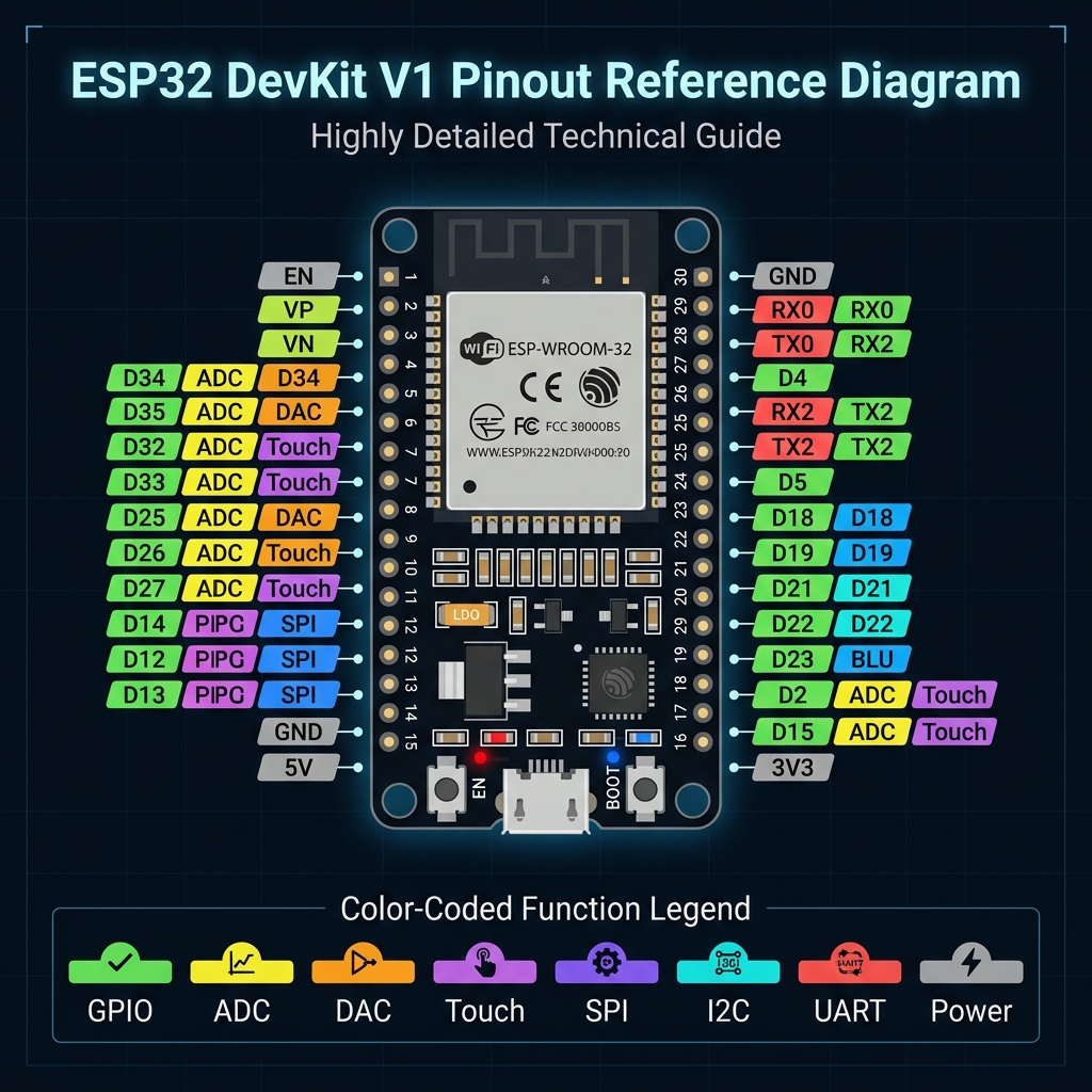
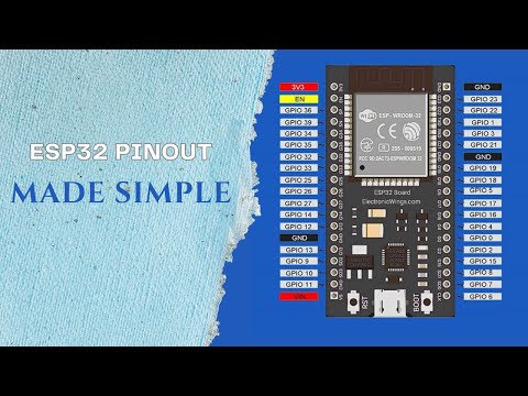
📌 Interactive Pin Explorer

Click any pin to learn about its capabilities:

Click a pin above to see its features and recommended uses.
ESP32 Pinout
Figure 1.3 — ESP32 DevKit V1 Pinout (color-coded by function)

ðŸŽĨ Video: Getting Started with ESP32

Getting Started with ESP32
Getting Started with ESP32 - Step-By-Step Tutorial
Tomasz Tarnowski
Module 2

Arduino IDE Setup

Install and configure the Arduino IDE to program your ESP32 board.

Arduino IDE
Figure 2.1 — Arduino IDE Interface

ðŸ“Ĩ Step-by-Step Installation

1
Download Arduino IDE

Go to arduino.cc/en/software and download the latest version for your operating system (Windows, macOS, or Linux).

2
Install & Launch

Run the installer and open the Arduino IDE. You'll see a blank sketch with setup() and loop() functions.

3
Add ESP32 Board Manager URL

Go to File → Preferences. In "Additional Board Manager URLs", paste:
https://espressif.github.io/arduino-esp32/package_esp32_index.json

4
Install ESP32 Board Package

Go to Tools → Board → Boards Manager. Search for "esp32" and install "esp32 by Espressif Systems".

5
Select Your Board

Go to Tools → Board → ESP32 Arduino and select "DOIT ESP32 DEVKIT V1" (or your specific board model).

6
Select COM Port

Connect your ESP32 via USB. Go to Tools → Port and select the COM port that appeared. If no port shows, install CP210x or CH340 USB drivers.

ðŸ’Ą Pro Tip

If your computer doesn't recognize the ESP32, you may need a data USB cable (not charge-only). Check the back of your board for the USB chip model (CP2102 or CH340) and install the correct driver.

ðŸŽĨ Video: Arduino IDE Installation

Arduino IDE Installation
How to Install Arduino IDE
Arduino Tutorial

ðŸŽĨ Video: ESP32 Board Setup in Arduino IDE

ESP32 Board Setup
ESP32 Board Setup in Arduino IDE
ESP32 Tutorial
Module 3

Your First Program

Write, upload, and understand the classic "Blink" program — the Hello World of microcontrollers.
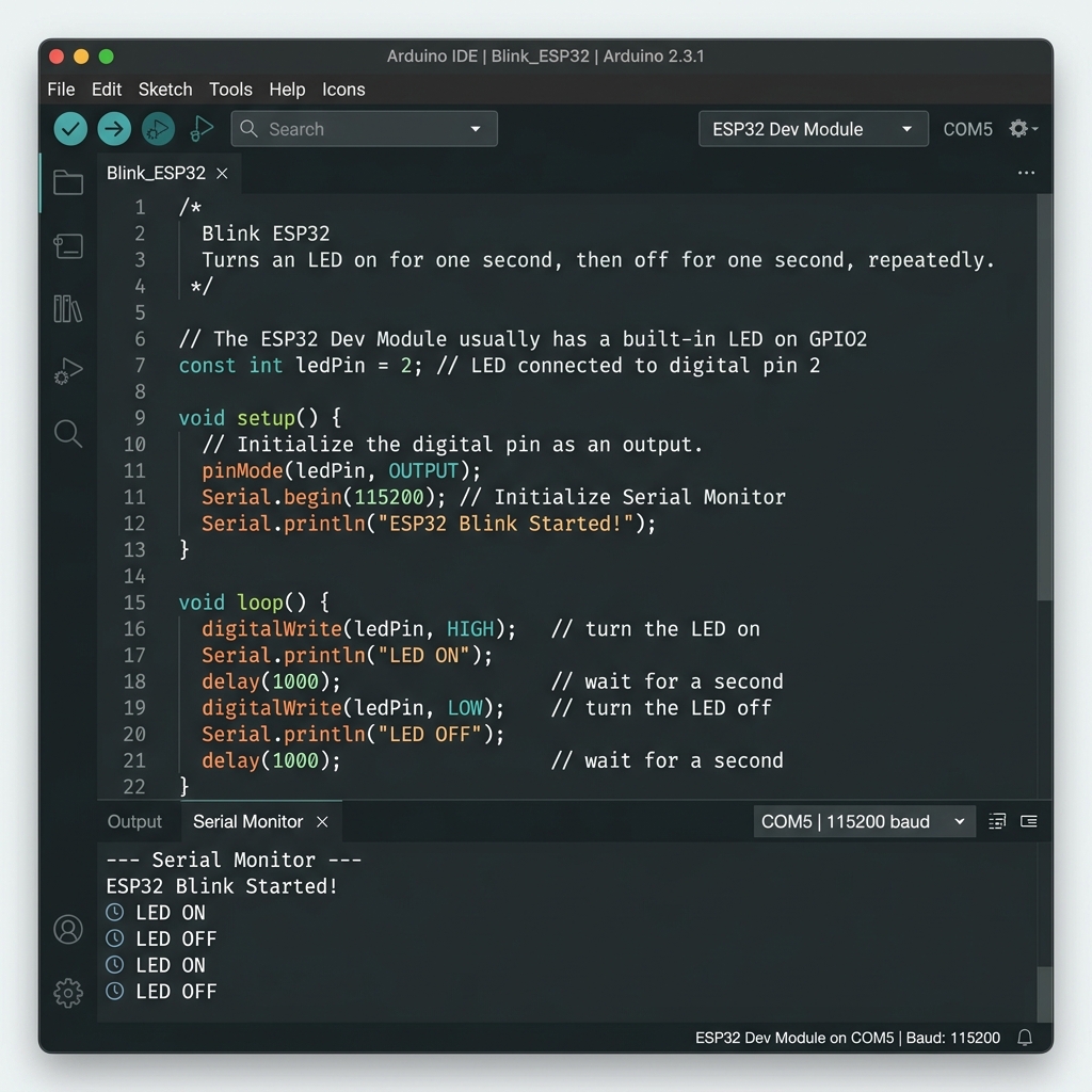
LED Circuit
Figure 3.1 — ESP32 LED blink circuit diagram

ðŸ’ŧ The Blink Sketch

This program makes the built-in LED on GPIO 2 blink on and off every second.

C++ / Arduino
// Define the LED pin #define LED_PIN 2 void setup() { pinMode(LED_PIN, OUTPUT); Serial.begin(115200); Serial.println("ESP32 Blink Program Started!"); } void loop() { digitalWrite(LED_PIN, HIGH); // Turn LED ON Serial.println("LED is ON"); delay(1000); // Wait 1 second digitalWrite(LED_PIN, LOW); // Turn LED OFF Serial.println("LED is OFF"); delay(1000); // Wait 1 second }

🔍 Code Breakdown

This is a preprocessor directive. Before your code is compiled, the preprocessor replaces every occurrence of LED_PIN with the number 2. GPIO 2 is where the built-in LED is connected on most ESP32 DevKit boards.
Runs once when the ESP32 starts. Use it for initialization: setting pin modes, starting serial communication, connecting to WiFi, etc.
Configures GPIO 2 as an OUTPUT pin, meaning it can send voltage out (to light an LED, control a motor, etc.).
Runs continuously in an infinite loop after setup() finishes. This is where your main program logic goes.
HIGH sends 3.3V to the pin (LED ON). LOW sends 0V (LED OFF). This is digital output — only two states.
Pauses the program for 1000 milliseconds (1 second). During this time, the ESP32 does nothing — in advanced programs, you'll learn to use millis() instead for non-blocking delays.

ðŸ’Ą Interactive LED Simulator

ðŸ”ī LED Simulator

LED State: OFF

ðŸŽĨ Video: ESP32 First Program

ESP32 First Program
ESP32 First Blink Program Tutorial
ESP32 Guide
🏆 Challenge

Modify the blink code to make the LED blink 3 times fast (200ms delay), then stay off for 2 seconds, and repeat. This simulates an SOS pattern!

Module 4

GPIO & Digital I/O

Learn how to read buttons and control multiple LEDs using digital input/output pins.

📖 Understanding GPIO

GPIO stands for General Purpose Input/Output. These are the pins on your ESP32 that you can configure to either:

  • OUTPUT — Send voltage out (e.g., turn on an LED, activate a motor)
  • INPUT — Read voltage in (e.g., detect a button press, read a sensor)
⚠ïļ Important

ESP32 GPIO pins operate at 3.3V, NOT 5V. Applying 5V to a GPIO pin can permanently damage the chip. Always use level shifters when interfacing with 5V devices.

🔘 Reading a Button

C++ / Arduino
#define BUTTON_PIN 15 #define LED_PIN 2 void setup() { pinMode(BUTTON_PIN, INPUT_PULLUP); pinMode(LED_PIN, OUTPUT); Serial.begin(115200); } void loop() { int state = digitalRead(BUTTON_PIN); if (state == LOW) { // Button pressed (active-low) digitalWrite(LED_PIN, HIGH); Serial.println("Button PRESSED"); } else { digitalWrite(LED_PIN, LOW); } delay(50); // Simple debounce }

ðŸšĶ Project: Traffic Light

C++ / Arduino
#define RED 25 #define YELLOW 26 #define GREEN 27 void setup() { pinMode(RED, OUTPUT); pinMode(YELLOW, OUTPUT); pinMode(GREEN, OUTPUT); } void loop() { digitalWrite(RED, HIGH); delay(5000); digitalWrite(RED, LOW); digitalWrite(GREEN, HIGH); delay(4000); digitalWrite(GREEN, LOW); digitalWrite(YELLOW, HIGH); delay(1500); digitalWrite(YELLOW, LOW); }

ðŸŽĨ Video: ESP32 GPIO Tutorial

ESP32 GPIO
ESP32 GPIO Pins Tutorial
ESP32 Guide
Module 5

Analog & PWM

Read analog sensors and control LED brightness using Pulse Width Modulation.

📊 Analog Input (ADC)

While digital pins only see HIGH or LOW, analog pins can read a range of values (0–4095 on ESP32's 12-bit ADC). This is essential for reading sensors like potentiometers, light sensors, and temperature sensors.

C++ / Arduino
#define POT_PIN 34 // ADC pin (input-only) void setup() { Serial.begin(115200); } void loop() { int value = analogRead(POT_PIN); float voltage = value * (3.3 / 4095.0); Serial.printf("Raw: %d | Voltage: %.2fV\n", value, voltage); delay(200); }

🌊 PWM Output

PWM (Pulse Width Modulation) simulates analog output by rapidly switching a digital pin on and off. The duty cycle determines how "bright" an LED appears or how "fast" a motor runs.

C++ / Arduino
#define LED_PIN 2 void setup() { ledcAttach(LED_PIN, 5000, 8); // pin, 5kHz freq, 8-bit res } void loop() { // Fade in for(int i = 0; i <= 255; i++) { ledcWrite(LED_PIN, i); delay(5); } // Fade out for(int i = 255; i >= 0; i--) { ledcWrite(LED_PIN, i); delay(5); } }

📈 PWM Waveform Visualizer

🌊 PWM Visualizer

ðŸŽĨ Video: ESP32 PWM Tutorial

ESP32 PWM
ESP32 PWM Tutorial — LED Dimming
Rui Santos
Module 6

Serial Communication

Debug your programs and communicate with your computer using the Serial Monitor.

ðŸ“Ą What is Serial Communication?

The Serial Monitor is your primary debugging tool. It creates a communication channel between your ESP32 and your computer over USB, allowing you to send and receive text messages.

C++ / Arduino
void setup() { Serial.begin(115200); // Set baud rate Serial.println("===== ESP32 Serial Demo ====="); Serial.println("Type a command and press Enter:"); Serial.println(" 'led on' → Turn LED on"); Serial.println(" 'led off' → Turn LED off"); Serial.println(" 'temp' → Read temperature"); } void loop() { if (Serial.available()) { String cmd = Serial.readStringUntil('\n'); cmd.trim(); if (cmd == "led on") { digitalWrite(2, HIGH); Serial.println("✓ LED turned ON"); } else if (cmd == "led off") { digitalWrite(2, LOW); Serial.println("✓ LED turned OFF"); } else { Serial.println("Unknown command: " + cmd); } } }

ðŸ–Ĩïļ Interactive Serial Simulator

Serial Monitor — 115200 baud
===== ESP32 Serial Demo ===== Type a command and press Enter: 'led on' → Turn LED on 'led off' → Turn LED off 'temp' → Read temperature 'status' → System status >

ðŸŽĨ Video: Arduino Serial Communication

Serial Communication
Arduino Serial Communication Basics
GreatScott!
Module 7

WiFi Basics

Connect your ESP32 to the internet and unlock the power of IoT.
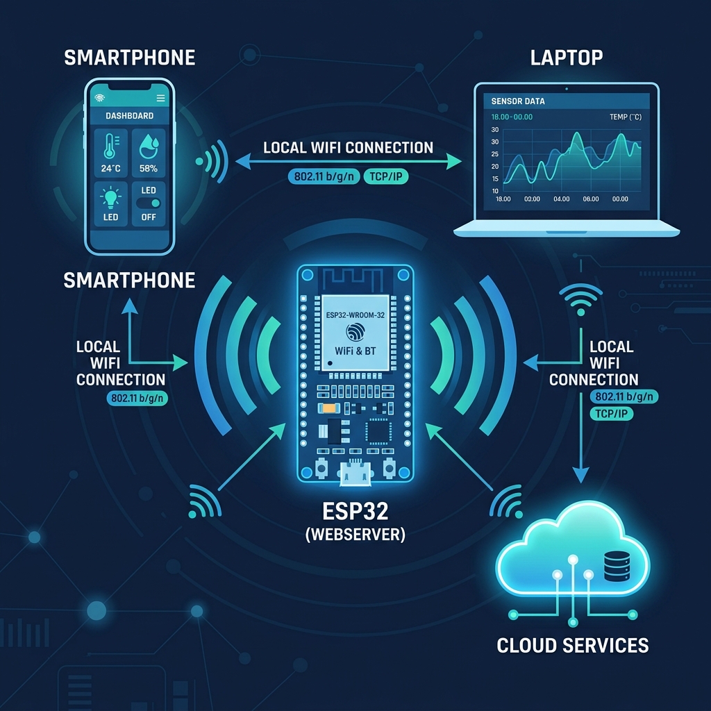
WiFi Concept
Figure 7.1 — ESP32 WiFi connectivity concept

ðŸ“ķ WiFi Station Mode

In Station Mode (STA), the ESP32 connects to your existing WiFi router — just like your phone or laptop does.

C++ / Arduino
#include <WiFi.h> const char* ssid = "YourNetwork"; const char* pass = "YourPassword"; void setup() { Serial.begin(115200); WiFi.begin(ssid, pass); Serial.print("Connecting"); while (WiFi.status() != WL_CONNECTED) { delay(500); Serial.print("."); } Serial.println("\n✓ Connected!"); Serial.print("IP Address: "); Serial.println(WiFi.localIP()); } void loop() {}

ðŸ“Ą Access Point Mode

In AP Mode, the ESP32 creates its own WiFi network. Devices can connect directly to it, no router needed!

C++ / Arduino
#include <WiFi.h> void setup() { Serial.begin(115200); WiFi.softAP("ESP32_Hotspot", "12345678"); Serial.print("AP IP: "); Serial.println(WiFi.softAPIP()); } void loop() {}

ðŸŽĨ Video: ESP32 WiFi Tutorial

ESP32 WiFi
ESP32 WiFi Station & Access Point
ESP32 Tutorial
Module 8

Web Server

Build a web interface to control your ESP32 from any browser on your network.

🌐 Complete Web Server Code

This creates a beautiful web page with buttons to toggle an LED, accessible from any device on your WiFi.

C++ / Arduino
#include <WiFi.h> #include <WebServer.h> const char* ssid = "YourNetwork"; const char* pass = "YourPassword"; WebServer server(80); bool ledState = false; String getHTML() { String html = "<!DOCTYPE html><html>"; html += "<head><meta name='viewport' "; html += "content='width=device-width'>"; html += "<style>body{font-family:Arial;"; html += "text-align:center;padding:40px;"; html += "background:#1a1a2e;color:white}"; html += ".btn{padding:20px 40px;font-size:18px;"; html += "border:none;border-radius:8px;"; html += "cursor:pointer;margin:10px}"; html += ".on{background:#4CAF50;color:white}"; html += ".off{background:#f44336;color:white}"; html += "</style></head><body>"; html += "<h1>ESP32 Web Control</h1>"; html += "<p>LED: " + String(ledState ? "ON":"OFF") + "</p>"; html += "<a href='/on'><button class='btn on'>ON</button></a>"; html += "<a href='/off'><button class='btn off'>OFF</button></a>"; html += "</body></html>"; return html; } void setup() { pinMode(2, OUTPUT); Serial.begin(115200); WiFi.begin(ssid, pass); while(WiFi.status() != WL_CONNECTED) delay(500); Serial.println(WiFi.localIP()); server.on("/", [](){ server.send(200,"text/html",getHTML()); }); server.on("/on", [](){ ledState=true; digitalWrite(2,HIGH); server.send(200,"text/html",getHTML()); }); server.on("/off", [](){ ledState=false; digitalWrite(2,LOW); server.send(200,"text/html",getHTML()); }); server.begin(); } void loop() { server.handleClient(); }

ðŸŽĨ Video: ESP32 Web Server

ESP32 Web Server
ESP32 Web Server — Beginner's Guide
DIY TechRush
Module 9

Sensors & Displays

Read environmental data with the DHT22 sensor and display it on an OLED screen.
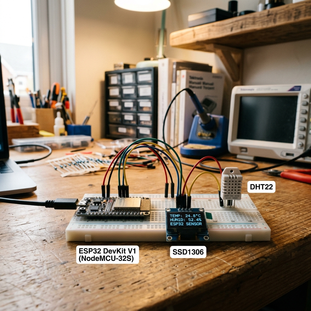
Sensor Project
Figure 9.1 — ESP32 with DHT22 sensor and OLED display

ðŸŒĄïļ DHT22 Temperature & Humidity

ðŸ“Ķ Required Libraries

Install via Arduino Library Manager: "DHT sensor library" by Adafruit and "Adafruit Unified Sensor".

C++ / Arduino
#include "DHT.h" #define DHT_PIN 4 #define DHT_TYPE DHT22 DHT dht(DHT_PIN, DHT_TYPE); void setup() { Serial.begin(115200); dht.begin(); } void loop() { float temp = dht.readTemperature(); float hum = dht.readHumidity(); if (!isnan(temp)) { Serial.printf("Temp: %.1f°C | Humidity: %.1f%%\n", temp, hum); } delay(2000); }

📚 OLED Display (SSD1306)

ðŸ“Ķ Required Libraries

Install: "Adafruit SSD1306" and "Adafruit GFX Library".

C++ / Arduino
#include <Wire.h> #include <Adafruit_GFX.h> #include <Adafruit_SSD1306.h> Adafruit_SSD1306 display(128, 64, &Wire, -1); void setup() { display.begin(SSD1306_SWITCHCAPVCC, 0x3C); display.clearDisplay(); display.setTextSize(2); display.setTextColor(WHITE); display.setCursor(0, 0); display.println("Hello!"); display.display(); }

ðŸŽĨ Video: ESP32 with OLED Display

ESP32 OLED
ESP32 OLED Display Tutorial
Rui Santos
Module 10 — Capstone

IoT Dashboard

Combine everything you've learned into a complete WiFi weather station with a web dashboard.

🏗ïļ Project Overview

This capstone project combines WiFi, Web Server, DHT22, and OLED into a complete IoT weather station. Your ESP32 will serve a beautiful live dashboard showing temperature, humidity, and historical data.

ðŸ’ŧ Complete Weather Station Code

C++ / Arduino
#include <WiFi.h> #include <WebServer.h> #include "DHT.h" const char* ssid = "YourNetwork"; const char* pass = "YourPassword"; WebServer server(80); DHT dht(4, DHT22); float temp = 0, hum = 0; String getDashboard() { String h = "<!DOCTYPE html><html><head>"; h += "<meta http-equiv='refresh' content='5'>"; h += "<style>body{font-family:Inter,sans-serif;"; h += "background:#030303;color:#fff;padding:40px;"; h += "text-align:center}"; h += ".card{background:rgba(255,255,255,0.03);"; h += "border:1px solid rgba(255,255,255,0.06);"; h += "border-radius:16px;padding:40px;margin:20px;"; h += "display:inline-block}"; h += ".val{font-size:48px;font-weight:800}"; h += "</style></head><body>"; h += "<h1>ðŸŒĪïļ ESP32 Weather Station</h1>"; h += "<div class='card'><div class='val'>"; h += String(temp,1) + "°C</div>Temperature</div>"; h += "<div class='card'><div class='val'>"; h += String(hum,1) + "%</div>Humidity</div>"; h += "</body></html>"; return h; } void setup() { Serial.begin(115200); dht.begin(); WiFi.begin(ssid, pass); while(WiFi.status()!=WL_CONNECTED) delay(500); Serial.println(WiFi.localIP()); server.on("/",[](){ server.send(200,"text/html",getDashboard()); }); server.begin(); } void loop() { temp = dht.readTemperature(); hum = dht.readHumidity(); server.handleClient(); delay(100); }

ðŸŽĨ Video: Complete IoT Project

ESP32 IoT Project
Complete ESP32 IoT WiFi Project
DIY TechRush
⭐ Interactive Lab

ESP32 Circuit Laboratory

Build real circuits on a virtual breadboard — drag components, draw wires between pins, and simulate your circuit to see it come alive!

â„đïļ How to Use the Lab

1. Drag components from the panel onto the breadboard.
2. Click "Wire Mode", then click on component pins (dots) to draw wires between them.
3. Choose wire colors to identify power (red), ground (blue), and signal (green) wires.
4. Click "Run" to simulate — the Serial Monitor will show real circuit behavior.
5. Hover a component to see its datasheet info in the bottom panel.

⚡ ESP32 Circuit Simulator
Wire:
🧰 Components
ðŸ”ē
ESP32 Board
30-pin DevKit
ðŸ”ī
Red LED
2V / 20mA
ðŸŸĒ
Green LED
2.1V / 20mA
ðŸ”ĩ
Blue LED
3.2V / 20mA
ðŸŸĄ
Yellow LED
2V / 20mA
⚡
220ÎĐ Resistor
Current limiter
⚡
10kÎĐ Resistor
Pull-up/down
🔘
Push Button
Tactile SPST
🎚ïļ
Potentiometer
10kÎĐ rotary
🔔
Piezo Buzzer
5V passive
ðŸŒĄïļ
DHT22 Sensor
Temp + Humidity
📚
OLED Display
128×64 I2C
⚙ïļ
Servo Motor
SG90 / 0°–180°
🔌
Relay Module
5V / 10A NO/NC
☀ïļ
LDR Sensor
Light dependent

Component Info

Hover over a component to see its details

🔌 Place components on the breadboard and click "Run" to see the output... ðŸ’Ą TIP: Use Wire Mode to connect component pins. The simulator will check your connections! 📋 EXPERIMENTS: Scroll down for guided step-by-step circuit projects.

📋 Guided Experiments
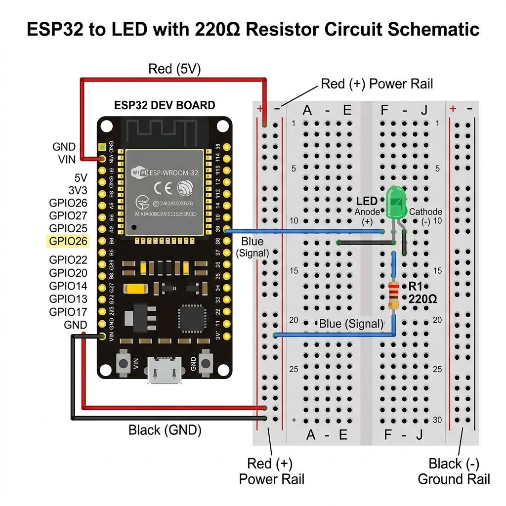
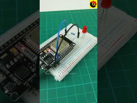
Experiment 1 — Beginner

ðŸ”ī Blink LED

Components: ESP32 + Red LED + 220ÎĐ Resistor
Wiring:
ðŸ”ī GPIO2 → 220ÎĐ Resistor (red wire)
ðŸŸĒ Resistor → LED Anode (green wire)
ðŸ”ĩ LED Cathode → GND (blue wire)
Result: LED blinks every second.

Experiment 2 — Beginner

ðŸšĶ Traffic Light

Components: ESP32 + 3 LEDs + 3 Resistors
Wiring:
ðŸ”ī GPIO25 → R1 → Red LED → GND
ðŸŸĄ GPIO26 → R2 → Yellow LED → GND
ðŸŸĒ GPIO27 → R3 → Green LED → GND
Result: Sequential traffic light pattern.

Experiment 3 — Intermediate

ðŸŒĄïļ Weather Station

Components: ESP32 + DHT22 + OLED
Wiring:
ðŸ”ī 3.3V → DHT22 VCC + OLED VCC
ðŸ”ĩ GND → DHT22 GND + OLED GND
ðŸŸĒ GPIO4 → DHT22 Data
ðŸŸĄ GPIO21 (SDA) → OLED SDA
ðŸŸĄ GPIO22 (SCL) → OLED SCL
Result: Live temp/humidity on OLED.

Experiment 4 — Beginner

🔘 Button + LED

Components: ESP32 + Button + LED + 2 Resistors
Wiring:
ðŸ”ī 3.3V → Button → GPIO15
ðŸŸĒ GPIO15 → 10kÎР→ GND (pull-down)
ðŸ”ĩ GPIO2 → 220ÎР→ LED → GND
Result: Press button to toggle LED.

Experiment 5 — Intermediate

🎚ïļ LED Dimmer (PWM)

Components: ESP32 + Pot + LED + Resistor
Wiring:
ðŸ”ī 3.3V → Pot VCC
ðŸ”ĩ GND → Pot GND
ðŸŸĄ Pot Wiper → GPIO34 (ADC)
ðŸŸĒ GPIO2 → 220ÎР→ LED → GND
Result: Rotate pot to dim LED via PWM.

Experiment 6 — Advanced

🔔 Smart Alarm

Components: ESP32 + LDR + Buzzer + OLED
Wiring:
ðŸ”ī 3.3V → LDR → GPIO34
ðŸŸĒ GPIO34 → 10kÎР→ GND (voltage divider)
ðŸ”ĩ GPIO13 → Buzzer → GND
ðŸŸĄ GPIO21/22 → OLED (I2C)
Result: Dark → alarm sounds + OLED alert.

Assessment

Final Quiz

Test your knowledge with 20 questions covering everything you've learned. Score 80% or higher to earn your certificate!

🎓 Your Certificate of Completion

Congratulations on completing the course! Download your official SGP certificate below.

SGP
SGPCARD.COM
Certificate of Completion

This is to certify that

Student Name

has successfully completed the ESP32 Programming Masterclass

A comprehensive course covering microcontroller programming, GPIO control, analog & PWM signals, serial communication, WiFi connectivity, sensor integration, and IoT project development

Verified
âœĶ
SGP