Master Electronics From Atoms to Circuits
Understand the invisible forces that power our world. From Ohm's Law to transistors, op-amps to PCB design — build real circuits with confidence.
📋 Course Overview
This course takes you from absolute beginner to confident electronics enthusiast. Each module builds upon the previous one, with hands-on calculators, interactive simulators, and video tutorials.
Electricity Basics
Voltage, current, resistance & power fundamentals
Ohm's Law
The foundation formula + interactive calculator
Resistors
Color codes, series/parallel & color band decoder
Capacitors
Charge/discharge, types & RC time constants
Inductors
Magnetic fields, RL circuits & transformers
Diodes
Rectifiers, Zener, LEDs & protection circuits
Transistors
BJT, MOSFET, amplifiers & switching
Op-Amps
Inverting, non-inverting, comparators
Logic Gates
AND, OR, NOT, NAND + truth table simulator
Power Supplies
Regulators, DC-DC converters, battery circuits
PCB Design
Schematic capture, layout & manufacturing
Circuit Lab
Ohm's Law, voltage divider & resistor calculators
Final Quiz
20 questions to test your knowledge
🧰 What You'll Need
Breadboard
Solderless breadboard for prototyping
Multimeter
Digital multimeter for measurements
LEDs & Resistors
Assorted LEDs, resistors, capacitors
Power Supply
5V/3.3V power source or battery pack
Jumper Wires
Male-male and male-female wires
Pliers & Cutter
Needle-nose pliers and wire stripper
Electricity Basics
Understand voltage, current, resistance and power — the four pillars of every electronic circuit.
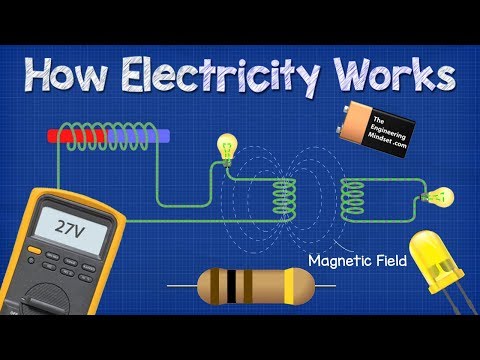
⚡ What is Electricity?
Electricity is the flow of electrons through a conductive material. Think of it like water flowing through a pipe — the pressure drives the flow, and the pipe's resistance controls how much water passes through.
Every atom has electrons orbiting its nucleus. In conductive materials like copper, the outermost electrons are loosely held and can move freely. When we apply a force (voltage), these electrons flow in one direction, creating an electric current.
🔋 Voltage (V) — The Pressure
Voltage is the electrical "pressure" that pushes electrons through a circuit. It's measured in Volts (V) and is the difference in electrical potential between two points.
Voltage is like the water pressure in a pipe. A higher water tank (higher voltage) creates more pressure, pushing water (electrons) through the pipe (wire) faster.
| Source | Voltage | Type |
|---|---|---|
| AA Battery | 1.5V | DC |
| USB Port | 5V | DC |
| Car Battery | 12V | DC |
| Wall Outlet (EU) | 230V | AC |
| Wall Outlet (US) | 120V | AC |
| Power Lines | 11,000V+ | AC |
🌊 Current (I) — The Flow
Current is the rate at which electrons flow through a conductor. It's measured in Amperes (A), often shortened to "amps". One ampere equals approximately 6.24 × 10¹⁸ electrons flowing past a point per second.
There are two types of current:
- DC (Direct Current) — Flows in one direction (batteries, solar panels, USB)
- AC (Alternating Current) — Changes direction periodically (wall outlets, power grid)
Current as low as 10 mA across the heart can be lethal. Always work with low voltages (under 50V DC) when learning. Never touch mains wiring. Use a circuit breaker and always turn off power before modifications.
🚧 Resistance (R) — The Opposition
Resistance opposes the flow of current. It's measured in Ohms (Ω). Every material has resistance — conductors like copper have very low resistance, while insulators like rubber have extremely high resistance.
| Material | Resistivity | Classification |
|---|---|---|
| Copper | 1.68 × 10⁻⁸ Ω·m | Conductor |
| Aluminum | 2.65 × 10⁻⁸ Ω·m | Conductor |
| Silicon | 6.40 × 10² Ω·m | Semiconductor |
| Glass | 10¹⁰ – 10¹⁴ Ω·m | Insulator |
| Rubber | 10¹³ Ω·m | Insulator |
💪 Power (P) — The Work Done
Power is the rate at which electrical energy is converted into another form (heat, light, motion). It's measured in Watts (W).
A 60W light bulb at 230V draws: I = P/V = 60/230 = 0.26A (260mA)
🎥 Video: Electricity Explained
Ohm's Law
The most important equation in electronics — plus Kirchhoff's voltage and current laws.
📐 Ohm's Law
Georg Simon Ohm discovered that voltage, current, and resistance are related by a beautifully simple formula:
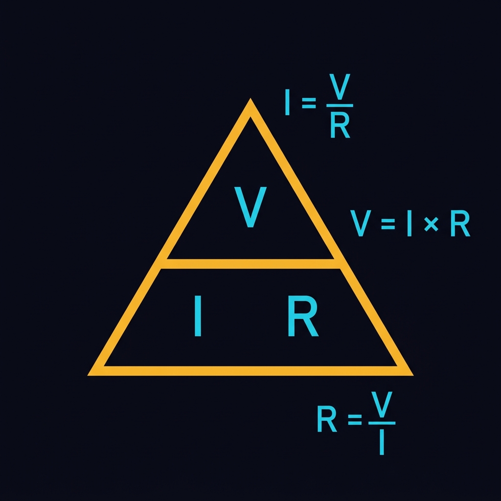
This can be rearranged to find any unknown:
- V = I × R — Find voltage (if you know current and resistance)
- I = V / R — Find current (if you know voltage and resistance)
- R = V / I — Find resistance (if you know voltage and current)
🧮 Interactive Ohm's Law Calculator
Enter any two values and click Calculate to find the third.
⚖️ Kirchhoff's Voltage Law (KVL)
The sum of all voltages around any closed loop in a circuit equals zero. In simple terms: the voltage supplied by the source is completely consumed by the components in the loop.
If you have a 9V battery and two resistors in series, the voltage drops across both resistors must add up to 9V. If R1 drops 3V, then R2 must drop 6V.
🔀 Kirchhoff's Current Law (KCL)
The total current entering a node (junction) equals the total current leaving that node. Current is neither created nor destroyed — it is conserved.
If 5A flows into a junction and splits into two paths, one carrying 3A, the other must carry 2A (3A + 2A = 5A).
🎥 Video: Ohm's Law

Resistors & Color Codes
Learn to read resistor values, understand series/parallel combinations, and use the interactive color code decoder.
🔩 What is a Resistor?
A resistor is a passive electronic component that limits the flow of current. It's the most common component in any circuit and is essential for protecting other components, dividing voltages, and setting bias points.
Resistors come in many types: carbon film, metal film, wire-wound, surface mount (SMD), and more. Through-hole resistors use a standard color band system to indicate their value.
🌈 Resistor Color Code
| Color | Digit | Multiplier | Tolerance |
|---|---|---|---|
| Black | 0 | ×1 | — |
| Brown | 1 | ×10 | ±1% |
| Red | 2 | ×100 | ±2% |
| Orange | 3 | ×1k | — |
| Yellow | 4 | ×10k | — |
| Green | 5 | ×100k | ±0.5% |
| Blue | 6 | ×1M | ±0.25% |
| Violet | 7 | ×10M | ±0.1% |
| Grey | 8 | — | — |
| White | 9 | — | — |
| Gold | — | ×0.1 | ±5% |
| Silver | — | ×0.01 | ±10% |
Bad Beer Rots Our Young Guts But Vodka Goes Well — Black, Brown, Red, Orange, Yellow, Green, Blue, Violet, Grey, White
🎨 Interactive Color Code Decoder
🔗 Series & Parallel Resistors
Series: Resistors in series add up directly.
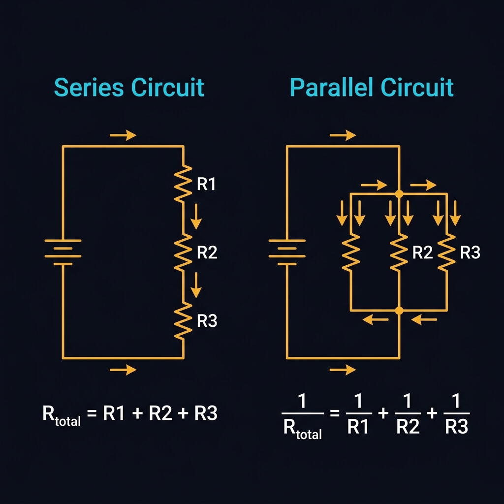
Parallel: The reciprocal of the total equals the sum of reciprocals.
For two resistors in parallel: R_total = (R1 × R2) / (R1 + R2). Two identical resistors in parallel give half the value.
🎥 Video: Resistors Explained

Capacitors & Energy Storage
Learn how capacitors store and release energy, their types, and RC time constants.
🔋 What is a Capacitor?
A capacitor stores electrical energy in an electric field between two conductive plates separated by an insulating material (dielectric). When voltage is applied, charge builds up on the plates. When disconnected, the capacitor retains the charge.
Capacitance is measured in Farads (F). Most capacitors are in the microfarad (µF), nanofarad (nF), or picofarad (pF) range.
📦 Types of Capacitors
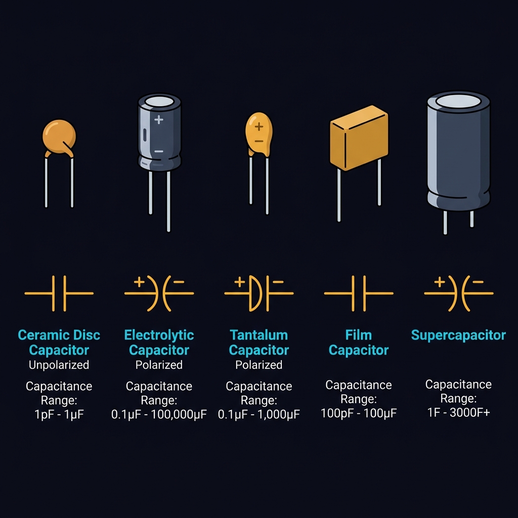
| Type | Capacitance Range | Polarized? | Common Use |
|---|---|---|---|
| Ceramic | 1pF – 10µF | No | Decoupling, filtering |
| Electrolytic | 0.1µF – 10,000µF | Yes ⚠️ | Power supply filtering |
| Tantalum | 0.1µF – 1,000µF | Yes ⚠️ | Precision circuits |
| Film | 100pF – 10µF | No | Audio, timing |
| Supercapacitor | 0.1F – 3000F | Yes | Energy backup |
Electrolytic and tantalum capacitors are polarized. Connecting them backwards can cause them to explode. Always check the positive (+) and negative (−) markings!
⏱️ RC Time Constant
When a capacitor charges through a resistor, it takes time. The time constant (τ) defines how quickly:
After 1τ: 63.2% charged. After 5τ: 99.3% charged (effectively full).
📊 Capacitor Charge Simulator
🎥 Video: Capacitors Explained

Inductors & Magnetic Fields
Discover how inductors store energy in magnetic fields and their role in filters, transformers, and power supplies.
🧲 What is an Inductor?
An inductor is a coil of wire that stores energy in a magnetic field when current flows through it. It resists changes in current — if current tries to increase, the inductor pushes back; if current tries to decrease, the inductor tries to maintain it.
Inductance is measured in Henrys (H), with practical values typically in millihenrys (mH) or microhenrys (µH).
⚡ RL Time Constant
Similar to RC circuits, RL circuits have a time constant:
After 5τ, the current reaches ~99.3% of its final value.
🔄 Transformers
A transformer uses two coupled inductors to transfer energy via magnetic induction. The voltage ratio equals the turns ratio:
Step-up transformers increase voltage (more secondary turns). Step-down transformers decrease voltage (fewer secondary turns). Transformers only work with AC!
🎥 Video: Inductors Explained

Diodes & Rectifiers
Understand the one-way valve of electronics — from signal rectification to LED lighting and voltage regulation.
➡️ What is a Diode?
A diode is a semiconductor device that allows current to flow in only one direction — from the anode (+) to the cathode (−). It acts as a one-way valve for electricity.
A silicon diode has a forward voltage drop of approximately 0.7V. Below this threshold, no current flows.
📦 Types of Diodes
| Type | V_forward | Key Use |
|---|---|---|
| Silicon (1N4007) | 0.7V | Rectification, protection |
| Schottky | 0.2–0.4V | Fast switching, power supplies |
| Zener | Varies | Voltage regulation (reverse bias) |
| LED | 1.8–3.3V | Light emission |
| Photodiode | — | Light detection |
🔀 Rectifier Circuits
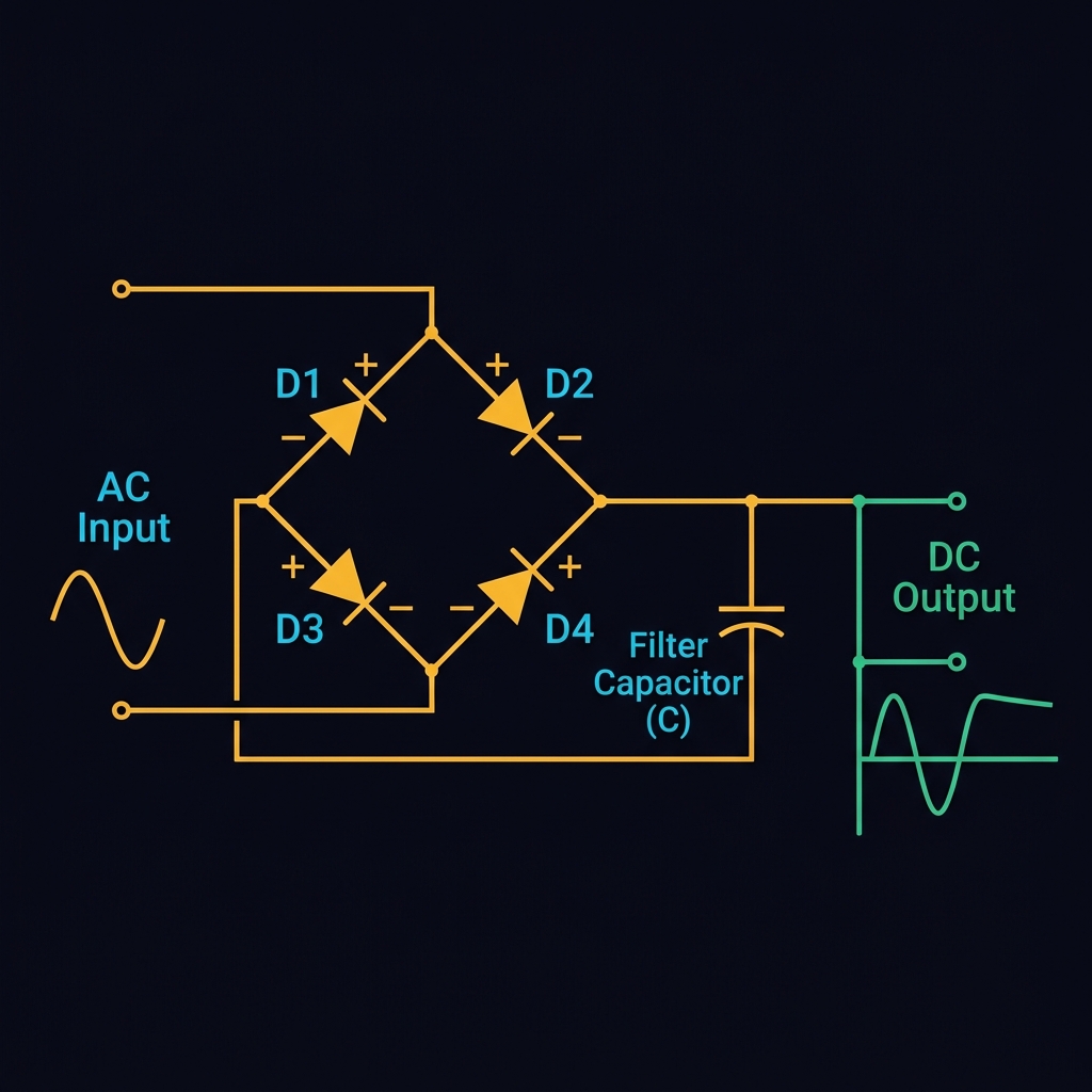
Diodes convert AC to DC through rectification:
- Half-wave rectifier — Uses 1 diode, passes only positive half-cycles. Simple but inefficient.
- Full-wave bridge rectifier — Uses 4 diodes, converts both half-cycles. Much more efficient and smooth.
Adding a filter capacitor after the rectifier smooths the pulsating DC into a more stable voltage.
💡 LEDs (Light Emitting Diodes)
LEDs emit light when current flows through them. They require a current-limiting resistor to prevent burnout.
Example: 5V supply, red LED (2V, 20mA): R = (5 − 2) / 0.02 = 150Ω (use 220Ω for safety).
🎥 Video: Diodes Explained

Transistors — The Building Block
The most important invention in electronics history. Learn BJT and MOSFET transistors for amplification and switching.
🧱 What is a Transistor?
A transistor is a semiconductor device that can amplify signals or act as an electronic switch. A small current or voltage at one terminal controls a much larger current between the other two terminals.
The transistor is arguably the most important invention of the 20th century — every computer chip contains billions of transistors.
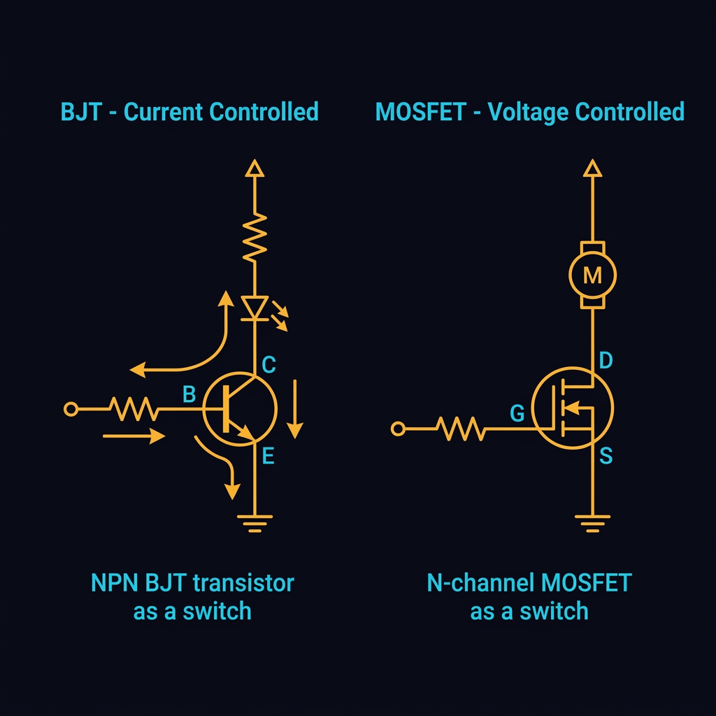
🔲 BJT (Bipolar Junction Transistor)
BJTs are current-controlled devices with three terminals:
- Base (B) — Control terminal (small current)
- Collector (C) — Main current input
- Emitter (E) — Main current output
Two types: NPN (most common, current into base turns it on) and PNP (current out of base turns it on).
A tiny base current (e.g., 0.1mA) can control a large collector current (e.g., 30mA) — that's amplification!
⚡ MOSFET (Metal-Oxide-Semiconductor FET)
MOSFETs are voltage-controlled devices — they're even more important in modern electronics:
- Gate (G) — Control terminal (voltage, no current!)
- Drain (D) — Main current input
- Source (S) — Main current output
MOSFETs switch with almost zero power loss at the gate, making them ideal for motor control, power supplies, and digital logic.
| Feature | BJT | MOSFET |
|---|---|---|
| Control | Current (I_B) | Voltage (V_GS) |
| Input impedance | Low (~kΩ) | Very high (~MΩ) |
| Speed | Fast | Very Fast |
| Best for | Linear amplification | Switching, power |
🎥 Video: Transistors Explained

Operational Amplifiers
Master the op-amp — a versatile integrated circuit used in amplifiers, filters, comparators, and more.
🔺 What is an Op-Amp?
An operational amplifier (op-amp) is a high-gain voltage amplifier IC with two inputs and one output. The most famous op-amp is the LM741, but modern designs like the LM358 and TL072 are common.
An ideal op-amp has: infinite gain, infinite input impedance, zero output impedance, and infinite bandwidth. Real op-amps approximate these ideal properties.
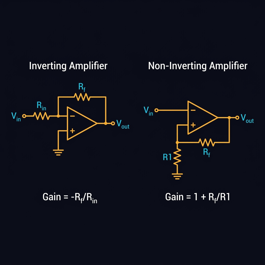
➖ Inverting Amplifier
The output is the inverted (negative) and amplified version of the input.
Example: R_f = 10kΩ, R_in = 1kΩ → Gain = −10. A 0.1V input produces −1V output (inverted and amplified 10×).
➕ Non-Inverting Amplifier
The output is a positive (non-inverted) amplified version of the input.
Example: R_f = 9kΩ, R_in = 1kΩ → Gain = 10. A 0.1V input produces +1V output.
⚖️ Comparator
An op-amp without feedback acts as a comparator. If V+ > V−, output goes HIGH. If V+ < V−, output goes LOW. Used in threshold detection, analog-to-digital conversion, and zero-crossing detectors.
🎥 Video: Op-Amps Explained
Digital Logic Gates
The foundation of all digital electronics — from simple gates to complex processors.
🔢 Binary & Digital Logic
Digital electronics works with two states: HIGH (1) and LOW (0). Logic gates process these binary inputs to produce an output based on Boolean algebra rules.
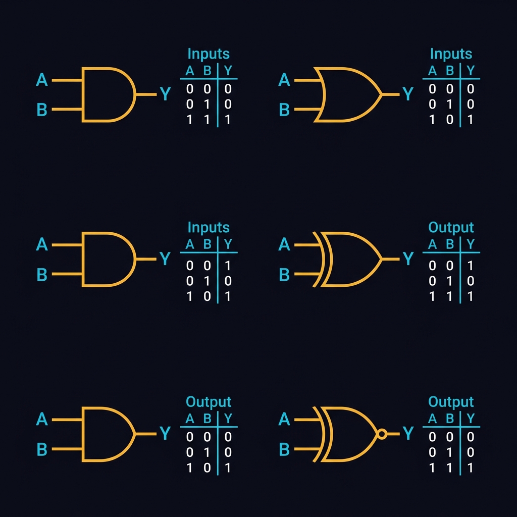
🚪 Basic Logic Gates
| Gate | Symbol | Function | Equation |
|---|---|---|---|
| AND | A · B | Output 1 only if ALL inputs are 1 | Y = A AND B |
| OR | A + B | Output 1 if ANY input is 1 | Y = A OR B |
| NOT | Ā | Inverts the input | Y = NOT A |
| NAND | (A·B)̄ | NOT of AND (universal gate) | Y = NOT(A AND B) |
| NOR | (A+B)̄ | NOT of OR (universal gate) | Y = NOT(A OR B) |
| XOR | A ⊕ B | Output 1 if inputs differ | Y = A XOR B |
🎮 Interactive Logic Gate Simulator
🎥 Video: Logic Gates

Power Supplies
Design reliable power sources — from linear regulators to switch-mode power supplies and battery management.
🔌 Power Supply Basics
Every electronic circuit needs a stable power supply. A typical power supply converts AC mains voltage to clean, regulated DC voltage through these stages:
Transformer
Steps down the AC mains voltage (230V/120V) to a lower AC voltage (e.g., 12V AC).
Rectification
Converts AC to pulsating DC using a bridge rectifier (4 diodes).
Filtering
Large electrolytic capacitor smooths the pulsating DC into a more stable voltage.
Regulation
Voltage regulator (e.g., LM7805) ensures a constant output voltage regardless of load changes.
📐 Linear Regulators
The 78xx series (e.g., 7805, 7812, 7833) are simple drop-out regulators. The last two digits indicate the output voltage.
| Part | Output | Max Current | Dropout |
|---|---|---|---|
| 7805 | 5V | 1.5A | ~2V |
| 7812 | 12V | 1.5A | ~2V |
| 7833 | 3.3V | 1.5A | ~2V |
| LM1117-3.3 | 3.3V | 0.8A | ~1.2V |
Linear regulators waste excess voltage as heat. P = (V_in − V_out) × I. A 12V→5V conversion at 1A wastes 7W as heat! Use a heatsink or consider a switching regulator for high-current applications.
🎥 Video: Power Supply Design
PCB Design
Turn your breadboard prototype into a professional printed circuit board — from schematic capture to manufacturing.
📋 PCB Design Workflow
Schematic Capture
Draw the circuit diagram using an EDA tool like KiCad, EasyEDA, or Altium. Define all components and their connections.
Component Footprints
Assign physical footprints (packages) to each schematic symbol — through-hole (THT) or surface-mount (SMD).
Board Layout
Place components on the PCB and route copper traces between them. Follow design rules for trace width, clearance, and via sizes.
Design Rule Check (DRC)
Verify the layout meets manufacturing constraints: minimum trace width, drill sizes, and clearances.
Generate Gerber Files
Export Gerber files — the industry-standard format that PCB manufacturers use to fabricate your board.
Manufacturing & Assembly
Send Gerber files to a PCB fab house (JLCPCB, PCBWay, OSHPark). Receive boards in 5-14 days and solder components.
🖥️ Recommended EDA Tools
| Tool | Price | Best For |
|---|---|---|
| KiCad | Free & Open Source | Professional-grade, unlimited layers |
| EasyEDA | Free (cloud) | Beginners, integrated with LCSC/JLCPCB |
| Altium Designer | $$$ | Industry standard, enterprise |
| Eagle | Free (limited) | Hobbyist, great community |
📏 PCB Design Rules
| Parameter | Standard | Fine Pitch |
|---|---|---|
| Trace Width | 0.254mm (10mil) | 0.127mm (5mil) |
| Trace Spacing | 0.254mm (10mil) | 0.127mm (5mil) |
| Via Drill | 0.3mm | 0.2mm |
| Via Pad | 0.6mm | 0.45mm |
| Board Thickness | 1.6mm | 0.8mm |
🎥 Video: KiCad PCB Design
Electronics Circuit Lab
Hands-on calculators and simulators for core electronics concepts — experiment and learn by doing!
⚡ Voltage Divider Calculator
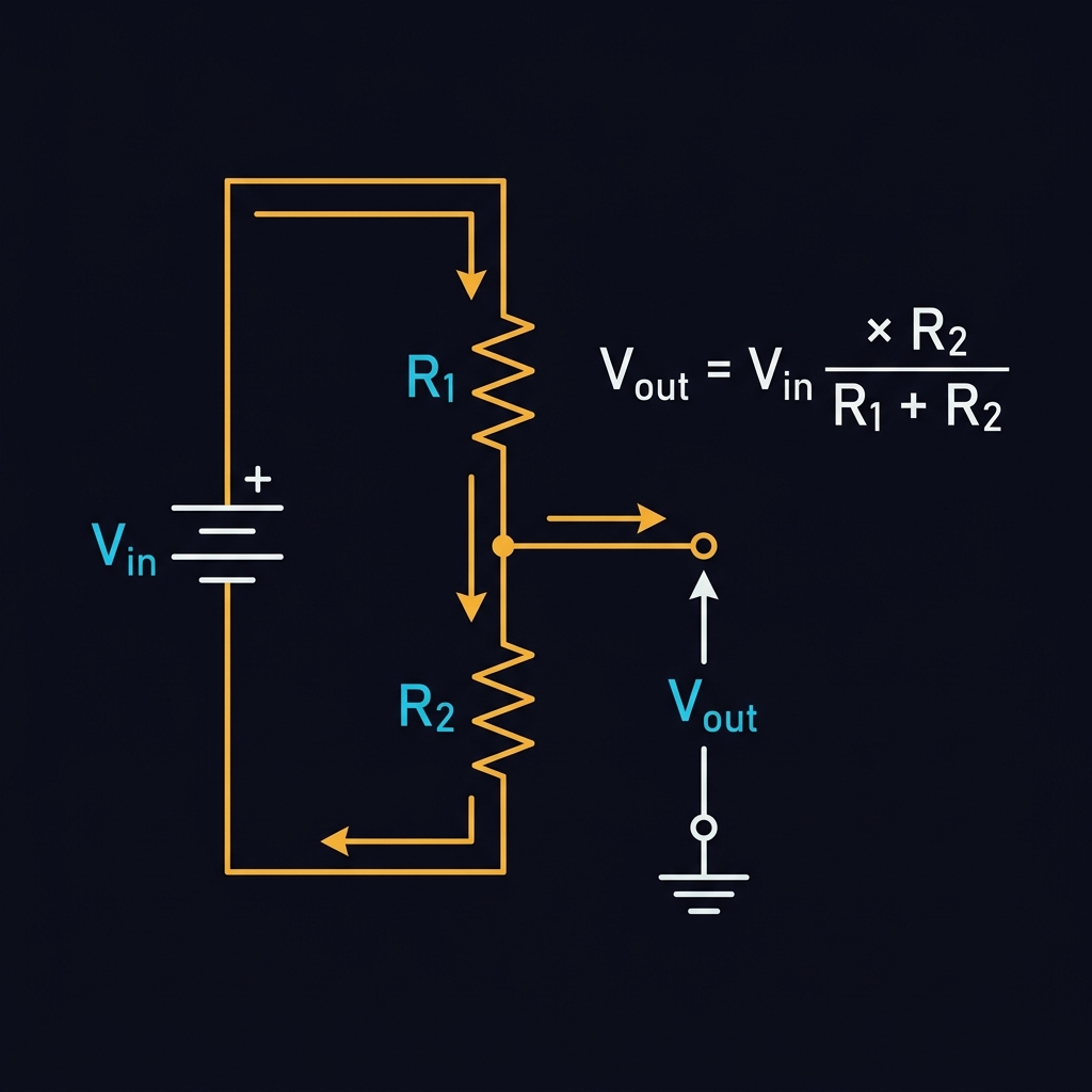
V_out = V_in × R2 / (R1 + R2)
💡 LED Resistor Calculator
Power dissipated: 60 mW — Use at least a 1/8W resistor
🔗 Parallel Resistor Calculator
Final Quiz
Test your knowledge with 20 questions covering everything you've learned. Score 80% or higher to earn your certificate!
🎓 Your Certificate of Completion
Congratulations on completing the course! Download your official SGP certificate below.

This is to certify that
has successfully completed the Electronics Masterclass
A comprehensive course covering electricity fundamentals, Ohm's Law, passive/active components, semiconductor devices, operational amplifiers, digital logic, power supply design, and PCB layout